phasefreq
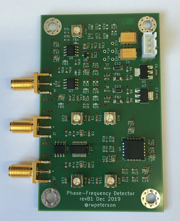
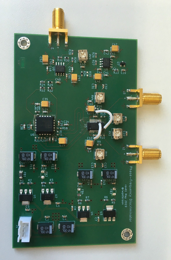
PCB implementing a phase-frequency detector as a standalone component
Quicklinks
Overview

This PCB design project implements a phase-frequency detector, which is basically a significant feature upgrade to an analog mixer. While an analog mixer's output is proportional to the phase between two signals, it has a limited range of stability in feedback applications of only 180 degrees, and if the two frequencies are initially distinct, it produces an oscillating signal that does not reliably drive them towards being equal. A phase-frequency detector uses flip-flops to produce a signal with a much wider capture range when locked, and when the frequencies differ, produces a constant signal driving them towards being equal.
While this functionality exists inside complex and featureful PLL ICs, it is often not exposed as a discrete unit, and those ICs that do so are typically quite expensive, and need to be initialized by a separate microcontroller on every power-up. The goal of this project is to provide a connectorized component that can be included in various rf test setups just like an analog mixer, without requiring anything extra besides power. The repo includes the design files, a BOM, a sketch for a 3D-printed enclosure, and characterization of an assembled board demonstrating both the wide capture range and constant frequency discrimination.

This project was a significant milestone for me—despite having designed PCBs and (especially analog) circuits for over a decade—since I made the leap to SMT components and reflow processing. (I blame my graduate institution, which had a comprehensive self-service stockroom of through-hole components.) I also got to experiment with Z-axis conductive tape, a remarkable tool that let me easily debug the first revision by sticking ICs to the PCB instead of doing delicate and time-consuming rework. For next time, I've since found a good PCB review checklist.